
OLPF in PTZ Cameras
What It Is, What It Does, and When You Actually Need It
Have you ever noticed strange rainbow patterns on a pinstripe suit, shimmering textures on an LED wall, or flickering lines on building facades in an otherwise sharp video image?
These distracting artifacts, known as moiré, become increasingly common as modern camera sensors pack more pixels into a limited space. Higher resolution improves detail, but it also makes cameras more prone to visual distortions that don’t exist in the real scene.
This is where the Optical Low-Pass Filter (OLPF) comes in. While some consumer cameras remove it for maximum sharpness, professional broadcast and Pro AV systems rely on OLPFs to maintain artifact-free clarity in high-end video workflows. In this guide, we'll explore how OLPFs work, why they matter, and whether they still have a place in today's high-resolution video workflows.
What Is an OLPF?
An Optical Low-Pass Filter — also referred to as an anti-aliasing filter or AA filter — is a optical component built into the camera body between the lens and the image sensor. Its function is precisely what the name describes: it filters out high-frequency spatial information from the incoming light before that light reaches the sensor, limiting the image data to frequencies the sensor is actually capable of resolving accurately.
The practical effect is a slight, controlled softening of the image at the optical level — not visible as blur under normal viewing conditions, but sufficient to prevent the interference patterns that occur when fine detail in the scene exceeds the sensor's sampling capacity.
Unlike software corrections applied in post-production, the OLPF operates entirely in the physical domain. It does not process the image after capture. It shapes the light before capture — which is the only point in the pipeline where certain categories of imaging artifact can be stopped entirely rather than merely reduced.
The Problem OLPF Solves: Moiré and False Color
To understand why OLPFs exist, it helps to understand what happens when they are absent — specifically, what occurs at the sensor level when the camera encounters certain types of visual information.
The Collision Between Two Regular Grids
A digital image sensor is, at its most fundamental level, a grid. Millions of photosites are arranged in precise, regular rows and columns, each one sampling the light falling on it and converting it to a numerical value. This regularity is what makes digital imaging possible — and it is also what makes certain subjects problematic.
When the camera is pointed at a subject that also has a regular, repeating structure — an LED wall, a woven fabric, a window blind, a brick facade shot at distance — two grids are now in the same optical system. The sensor grid and the subject pattern interact. Depending on the relationship between their respective frequencies, this interaction produces interference: a third pattern that exists in neither the sensor nor the subject, but emerges from their combination.
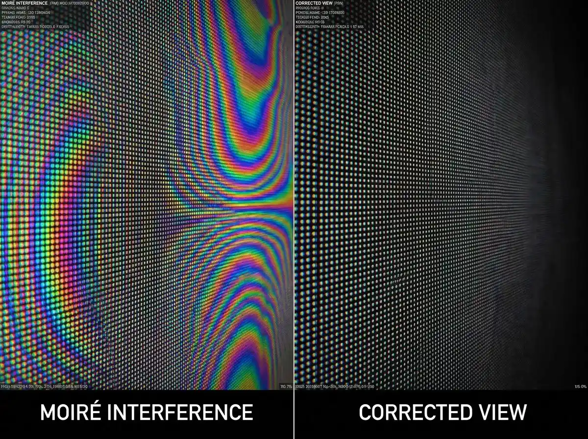
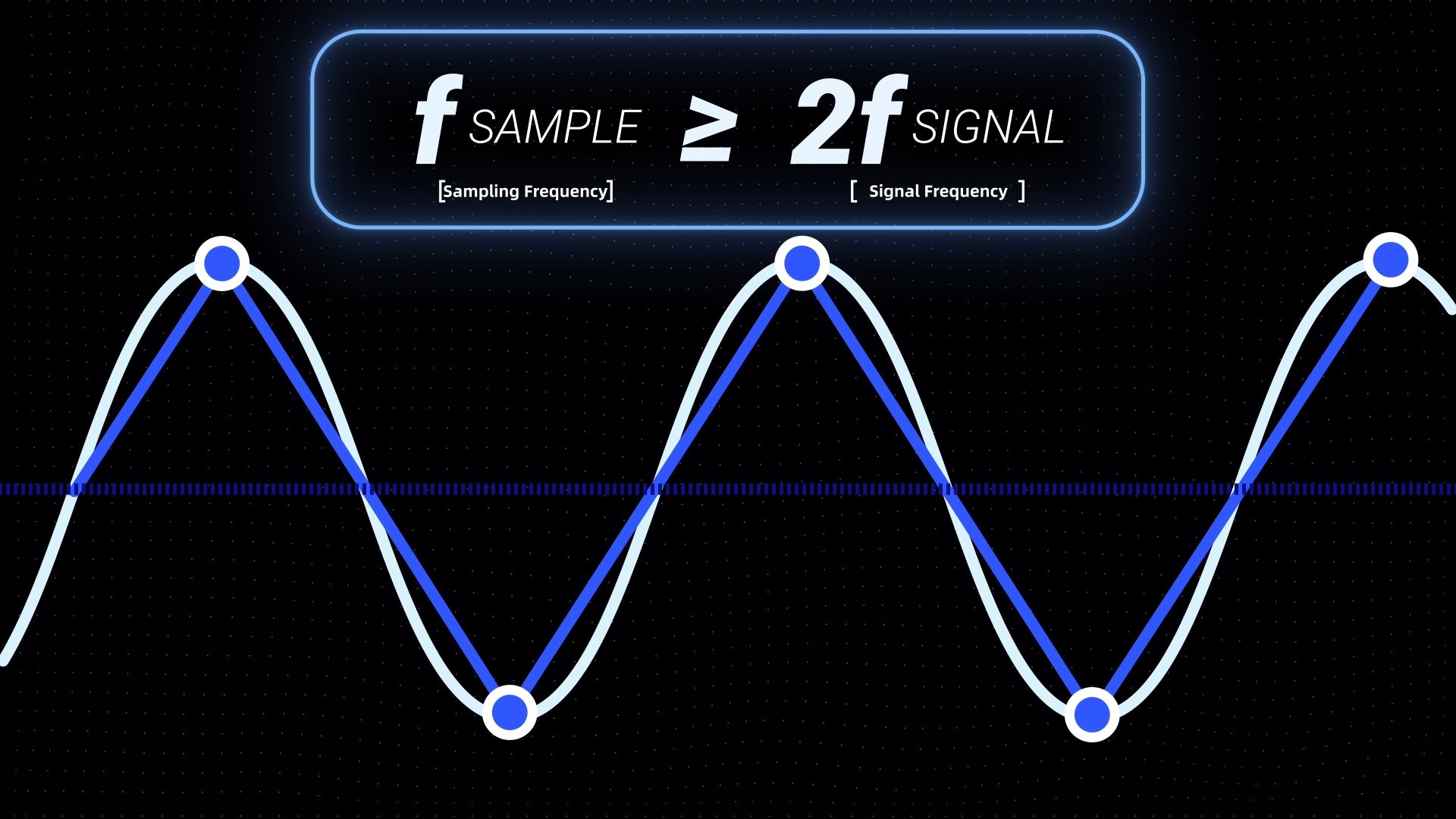
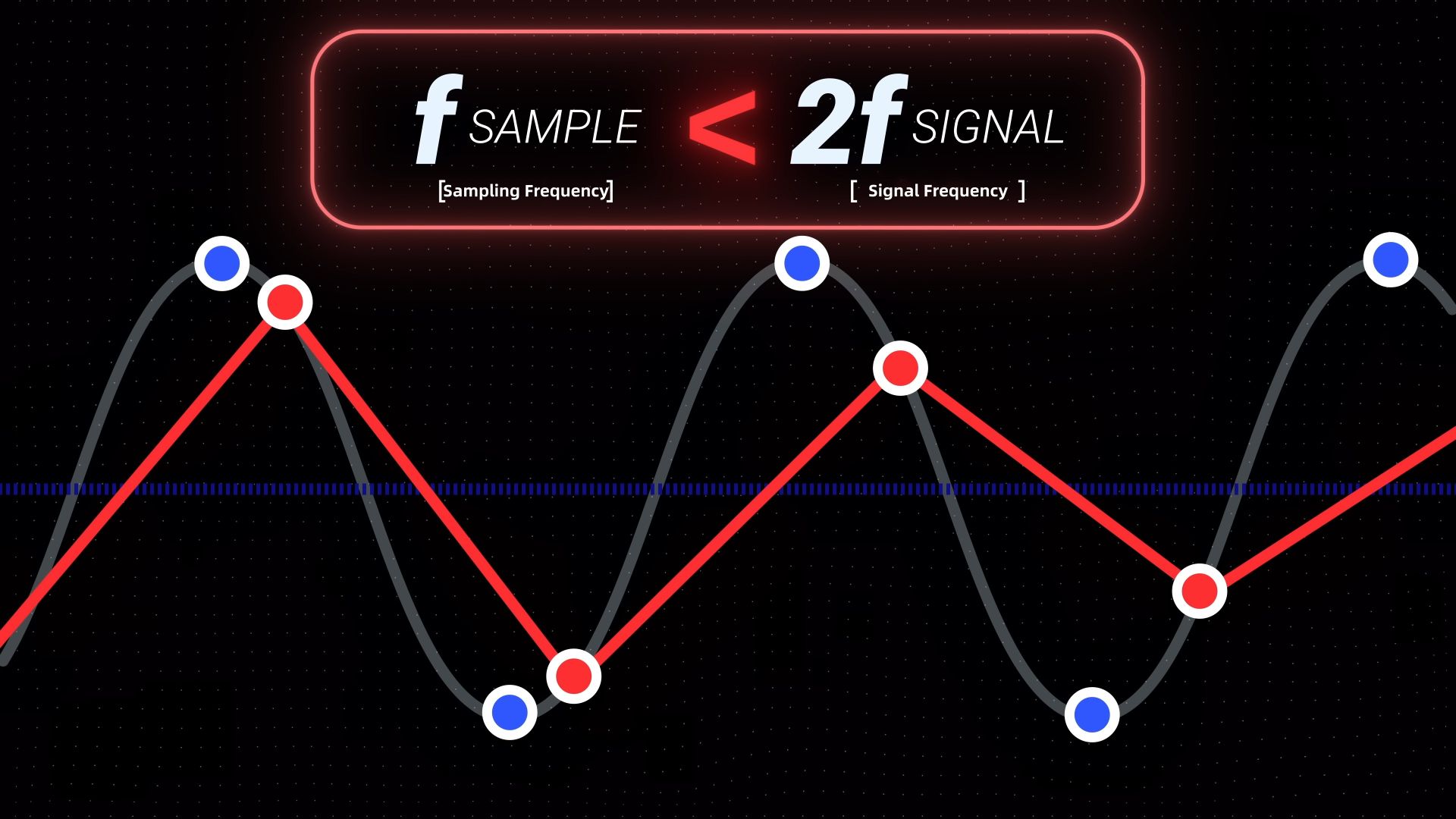
This phenomenon is not unique to cameras. It is a fundamental property of any sampling system encountering a signal that approaches or exceeds its sampling frequency limit — a relationship described mathematically by the Nyquist-Shannon sampling theorem. The theorem establishes a precise threshold: to accurately reconstruct a signal, the sampling frequency must be greater than twice the highest frequency component of the incoming signal. In imaging terms, this means a sensor's pixel sampling rate must be at least twice the spatial frequency of the finest detail in the scene for that detail to be recorded without error. The point at which incoming spatial frequency reaches half the sensor's sampling rate is known as the Nyquist frequency — and it defines the boundary beyond which accurate reproduction becomes impossible.
When scene detail exceeds this threshold, the excess spatial frequency information does not simply disappear. It folds back into the image as a misrepresented lower-frequency signal — a process known as aliasing. In imaging, aliasing is the root cause of both moiré patterns and false color: the sensor is not malfunctioning; it is faithfully recording data it does not have sufficient resolution to interpret correctly.
This is also why the filter designed to prevent it carries the name it does. An anti-aliasing filter — the OLPF — intervenes before aliasing can occur, removing the spatial frequencies that would exceed the sensor's Nyquist limit before they ever reach the photosite array.
Moiré: The Pattern That Moves
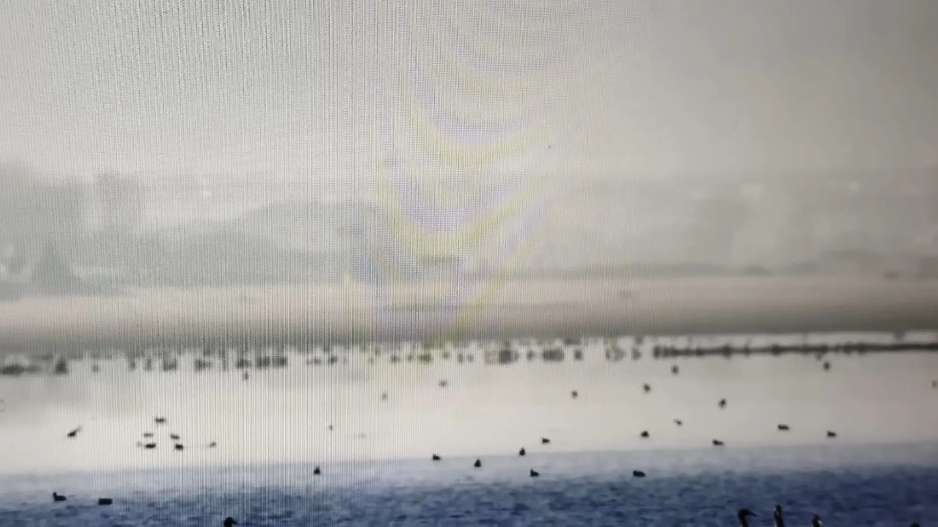
The most visible form of this artifact is moiré — the wave-like, often iridescent pattern that appears across fine regular structures in the frame. In still photography, moiré is a nuisance. In video, it is significantly more disruptive.
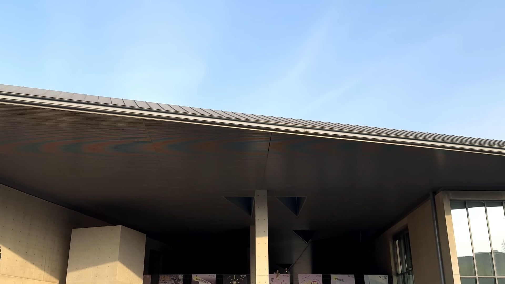
The reason is motion. In a static image, moiré appears as a fixed pattern that the viewer can mentally discount once they recognize it. In video, as the camera makes even minor adjustments — a slight pan, a zoom increment, a change in subject distance — the interference relationship between the two grids shifts continuously. The moiré pattern does not stay still. It drifts, ripples, and pulses across the frame in a way that draws the eye persistently and resists post-production correction.
This motion characteristic is what makes moiré particularly consequential in PTZ camera deployments, where pan and tilt movements are frequent and the camera's relationship to its background is constantly changing.
False Color: The Artifact You Did Not Put There
The second category of artifact that OLPFs address is false color — chromatic information that appears in the recorded image but was not present in the original scene.
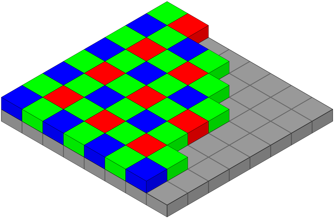
False color originates in the demosaicing process. Most digital sensors use a Bayer color filter array, in which individual photosites are covered by red, green, or blue filters arranged in a specific pattern. No single photosite captures full color information — instead, the camera's processor interpolates color values for each pixel by sampling its neighbors. This interpolation works reliably when the spatial frequencies in the scene are within the sensor's resolving capacity.
When they are not — when fine detail exceeds the Nyquist limit — the interpolation algorithm encounters ambiguous data and produces incorrect color assignments. The result is pixels with color values that have no correspondence to anything in the actual scene: fringing along high-contrast edges, unexpected color bands across fine patterns, or chromatic noise in areas that should be neutral.
Unlike moiré, false color is not always immediately obvious to the viewer. It tends to manifest as a subtle but persistent degradation of color accuracy in areas of fine detail — the kind of problem that becomes apparent in critical review or on a calibrated display, but may go unnoticed in a real-time monitor.
Why Video Is More Vulnerable Than Still Photography
It might seem counterintuitive that video — which operates at lower resolutions than modern still cameras — would be more susceptible to these artifacts. The explanation lies in the relationship between resolution and sampling frequency.
A 4K video frame contains approximately 8 megapixels of information. A contemporary still camera sensor routinely captures 24, 45, or even 60 megapixels per frame. At higher pixel counts, the sensor's sampling frequency increases, raising the threshold at which incoming spatial frequencies become problematic. Fine detail that would cause moiré on an 8-megapixel sensor may be resolved cleanly on a 45-megapixel sensor because the pixel grid is dense enough to sample it accurately.
Video sensors, operating at 4K or even 6K, sit closer to the problematic frequency range for a much wider variety of real-world subjects. The threshold for artifact generation is lower, the range of subjects that can trigger it is broader, and the motion characteristic of video makes the resulting artifacts more visible than their still-image equivalents.
This is why OLPFs remained standard in professional video cameras long after consumer still cameras began removing them — and why the question of OLPF inclusion is particularly consequential in the PTZ camera category, where the production environments involved routinely include the subject types most likely to trigger both moiré and false color.
How OLPF Works
The function of an OLPF is straightforward in principle: reduce the spatial frequency of incoming light to a level the sensor can sample without error. The method by which it achieves this is optical rather than electronic, which is precisely what makes it effective at a stage of the imaging pipeline where software cannot intervene.
Birefringent Crystals and Controlled Light Splitting
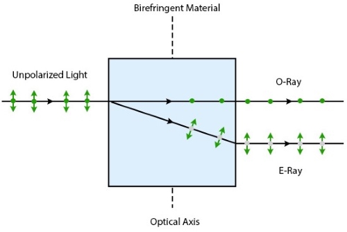
The core component of most OLPFs is a birefringent crystal — a material with the optical property of splitting a single ray of incoming light into two distinct components. When an unpolarized light ray enters the crystal, it separates into two beams traveling at slightly different velocities and along slightly different paths: the ordinary ray (O ray), which propagates according to standard refraction principles regardless of the crystal's orientation, and the extraordinary ray (E ray), whose propagation velocity and direction are determined by the crystal's optical axis. The two rays exit the crystal spatially offset from one another by a precise, controlled distance determined by the crystal's thickness and orientation.
The result is that each point of the image is duplicated at a sub-pixel separation — one instance carried by the O ray, one by the E ray — spreading what would otherwise be a single concentrated point of high-frequency detail across two adjacent photosites. Stacked layers of birefringent crystal, typically oriented at different axes, extend this splitting in both horizontal and vertical directions, producing a controlled softening of the image that is uniform across the sensor plane.
This is not accidental blurring. The separation distance is engineered to correspond specifically to the sensor's pixel pitch, so that the splitting occurs at exactly the spatial frequency that would otherwise produce aliasing. High-frequency detail that would exceed the Nyquist limit is effectively averaged across neighboring photosites before it can generate an interference pattern — removing the problematic frequencies at the optical level, before the sensor ever records them.
What This Means in Practice
The result of this process is an image that reaches the sensor with its spatial frequency content already band-limited to what the pixel array can resolve accurately. Moiré patterns and false color cannot form because the frequencies that would generate them have been attenuated before reaching the photosite array. The sensor records a clean signal — not because the problematic detail has been corrected, but because it was never presented to the sensor in a form that could cause problems.
The trade-off is inherent in the mechanism. Splitting each point of light across two photosites means that the finest resolvable detail in the image is slightly softer than it would be without the filter. The OLPF cannot selectively suppress only the frequencies that would cause aliasing while leaving all others intact — the softening applies across the high-frequency range as a whole.
In practice, this trade-off is the central tension in any discussion of OLPF design: how much high-frequency attenuation is necessary to reliably prevent aliasing, and how much sharpness loss does that level of attenuation introduce? It is a question without a universal answer — which is why the next section addresses it directly.
The Trade-off: Sharpness vs. Image Cleanliness
Every OLPF introduces a measurable reduction in optical sharpness. This is not a design flaw — it is an inherent consequence of the light-splitting mechanism described in the previous section. The question is whether that reduction is an acceptable trade-off given the production environment the camera will operate in.
The short answer is: it depends entirely on what the camera will be pointing at.
In environments with high-frequency patterns — LED walls, textured backgrounds, screen-heavy sets — the absence of an OLPF creates a moiré risk that is visible, recurring, and resistant to post-production correction. In controlled environments with simple backgrounds, the same camera without an OLPF will likely never encounter conditions that trigger the problem, and the sharpness advantage becomes the more relevant factor.
The table below maps these trade-offs across the dimensions that matter most in professional PTZ deployments.
The takeaway is not that one configuration is superior. It is that the correct choice is determined by the production environment — which is what the following sections address directly.
Why PTZ Cameras Are Particularly Exposed to Moiré — And When OLPF Matters
PTZ cameras occupy a specific position in the production landscape that makes moiré risk unusually relevant. Unlike cinema cameras or ENG cameras that move with a dedicated operator through varied environments, PTZ cameras are fixed installations — deployed once, configured once, and expected to perform reliably across every session in that space, often without an operator present to identify or compensate for artifact problems in real time.
The environments where PTZ cameras are most commonly installed — houses of worship, corporate studios, hybrid meeting rooms, virtual production sets — share a common characteristic: they are built around LED displays, screen-heavy backgrounds, and structured architectural detail. These are precisely the conditions under which aliasing artifacts occur most reliably and most visibly.
This is why OLPF has shifted from a premium feature to a practical necessity in broadcast-grade PTZ cameras. Whether it is necessary for your specific deployment comes down to one question: what is behind your subject?
Strongly Recommended
• LED walls or LED display screens appearing in the background
• Houses of worship with stage displays or architecturally complex backdrops
• Broadcast studios where presenters regularly wear fine-pattern clothing
• Corporate event spaces with display screens or structured decorative backgrounds
• Fashion or apparel content where fabric texture is frequently in frame
Likely Not Necessary
• The background is a plain painted wall or whiteboard
• The deployment environment is fully controlled with simple, pattern-free backgrounds
• Budget constraints apply and the shooting conditions are predictable and low-risk
For productions in the first category, Telycam's Explore 300 and Explore 500 both include an integrated OLPF as part of their broadcast-grade optical stack — addressing moiré at the hardware level without requiring post-production intervention. For simpler deployment environments, models without OLPF remain a practical and cost-effective choice.
Frequently Asked Questions
Conclusion
Moiré and false color are not random image defects. They are predictable results of how a camera sensor interacts with fine repeating patterns such as LED walls, fabrics, architectural details, and display screens.
That is why OLPFs remain relevant even in the era of high-resolution sensors. By filtering problematic spatial frequencies before they reach the sensor, an OLPF helps prevent artifacts that are difficult—or often impossible—to remove later in the workflow.
Ultimately, the decision comes down to the shooting environment. For PTZ cameras used in education, houses of worship, corporate AV, live events, and other unattended production scenarios, image consistency is often more valuable than extracting the last bit of sharpness. In those situations, a well-designed OLPF can be the difference between footage that looks clean and professional and footage that is constantly fighting visible artifacts.